
ການຈັດສົ່ງຄວາມກົດດັນທີ່ບໍ່ເທົ່າທຽມກັນມີຜົນຕໍ່ການຫຼືນຂອງເຮຊິນ ແລະ ການປະສົມປະສານຂອງໄຟເບີ
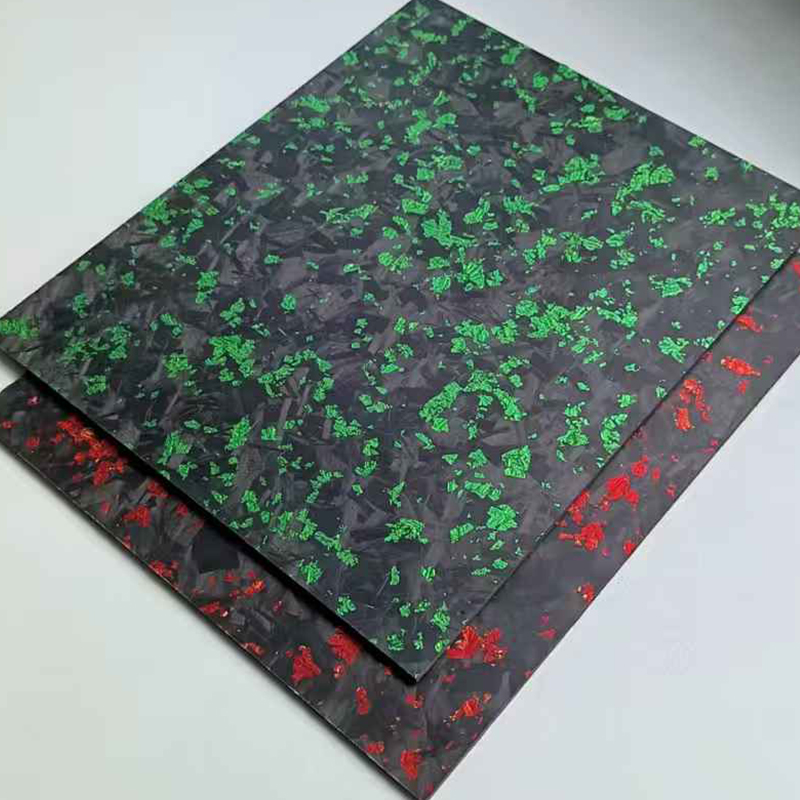
ເມື່ອການນຳໃຊ້ຄວາມດັນບໍ່ເປັນປະກົດຢ່າງຕໍ່ເນື່ອງໃນຂະບວນການລາມິເນດແຜ່ນໄຟເບີກາໂບນ ການຫຼືນໄຫຼຂອງເຮືອນເຄມີ (resin) ແລະ ການປະສົມປະສານຂອງໄຟເບີຈະຖືກຮຸກຮານ ແລະ ບັນຫານີ້ທີ່ແທ້ຈິງແລ້ວເຂົ້າໃຈໄດ້ງ່າຍຫຼາຍ: ເຮືອນເຄມີມີແນວໂນ້ມທີ່ຈະຫຼືນໄຫຼໄປຫາບໍລິເວນທີ່ມີຄວາມດັນຕ່ຳກວ່າ ເຊິ່ງໝາຍຄວາມວ່າບາງບໍລິເວນຈະ 'ຂາດເຮືອນເຄມີ' ໃນຂະນະທີ່ບໍລິເວນອື່ນຈະມີເຮືອນເຄມີຫຼາຍເກີນໄປ. ຈຸດທີ່ໄຟເບີເປີດເຜີຍອອກມາ ('dry spots') ຈະເກີດຂຶ້ນ ໃນຂະນະທີ່ການຫຼືນໄຫຼຂອງເຮືອນເຄມີເຂົ້າໄປໃນບໍລິເວນຕ່າງໆ ມີຫຼາຍເກີນໄປ. ຂະບວນການທັງໝົດຈະເສຍຄວາມສົມດຸນເນື່ອງຈາກການບີບອັດໄຟເບີທີ່ບໍ່ເທົ່າກັນ ເຊິ່ງຈະເຮັດໃຫ້ການຈັບຕິດລະຫວ່າງຊັ້ນອ່ອນລົງເສຍຫຼງ ແລະ ຄວາມເຂັ້ມແຂງ ຫຼື ຄວາມໝັ້ນຄົງດ້ານໂຄງສ້າງຂອງຊິ້ນສ່ວນຫຼຸດລົງ. ຂໍ້ມູນຈາກອຸດສາຫະກຳບອກວ່າ ຄວາມແຕກຕ່າງຂອງຄວາມດັນທີ່ບໍ່ເທົ່າກັນພຽງແຕ່ 15% ທົ່ວທັງຊັ້ນລາມິເນດ (laminate) ອາດຈະຫຼຸດລົງຄວາມເຂັ້ມແຂງໃນທິດທາງດຶງ (tensile strength) ໄດ້ເຖິງ 30%. ການບັນລຸຄວາມສົມດຸນໃນການນຳໃຊ້ຄວາມດັນຈຶ່ງເປັນສິ່ງທີ່ສຳຄັນທີ່ສຸດເພື່ອຮັບປະກັນວ່າເຮືອນເຄມີຈະສາມາດຫຼືນໄຫຼໄດ້ຢ່າງເທົ່າທຽມກັນທົ່ວທັງໄຟເບີ ເຊິ່ງຈະເຮັດໃຫ້ການຈັບຕິດທີ່ຖືກຕ້ອງລະຫວ່າງເຮືອນເຄມີກັບເມັດຕາຣິກ (resin matrix) ເກີດຂຶ້ນໄດ້ ແລະ ສົ່ງເສີມຄວາມເຂັ້ມແຂງ ແລະ ຄວາມທົນທານຂອງຊິ້ນສ່ວນທີ່ສຳເລັດ.
ບໍ່ເຕັມ, ແຖບແຫ້ງ, ແລະ ຄວາມໜາທີ່ບໍ່ສອດຄ່ອງກັນ ອັນເກີດຈາກຄວາມແຕກຕ່າງຂອງຄວາມກົດດັນ.
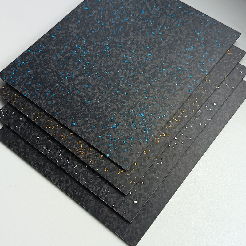
ໃນຂະນະທີ່ຜະລິດ, ຄວາມແຕກຕ່າງຂອງຄວາມກົດດັນຈະເຮັດໃຫ້ເກີດບັນຫາຄຸນນະພາບທີ່ຮ້າຍແຮງ. ເຂດທີ່ມີຄວາມກົດດັນຕ່ຳມັກຈະເກີດຖົງອາກາດ, ເຊິ່ງເຮັດໃຫ້ຈຳນວນຂອງບໍ່ເຕັມໃນວັດສະດຸປະກອບເພີ່ມຂຶ້ນ. ຕາມທີ່ Composites Today ປີ 2023 ໄດ້ລາຍງານ, ການປ່ຽນແປງຄວາມກົດດັນເຖິງ 5% ສາມາດເຮັດໃຫ້ຈຳນວນບໍ່ເຕັມເພີ່ມຂຶ້ນ 7-12%. ເມື່ອເຮືອນຢາງບໍ່ສາມາດເຕີມເຂົ້າໄປໃນບ່ອນໜຶ່ງຂອງແມ່ພິມໄດ້ພໍ, ບ່ອນແຫ້ງຈະເກີດຂຶ້ນໂດຍສະເພາະແຕ່ບໍລິເວນແຖວຂອງແມ່ພິມທີ່ຄວາມກົດດັນຕ່ຳ. ບາງເຂດຈະຖືກບີບອັດ ແລະ ບາງເຂດຈະຫນາຂຶ້ນ, ຈຶ່ງເກີດບ່ອນແຫ້ງ. ຄວາມບໍ່ສອດຄ່ອງກັນຂອງວັດສະດຸເຮັດໃຫ້ເກີດຄວາມເຄັ່ນຄວາຍທີ່ບໍ່ສອດຄ່ອງກັນ ແລະ ທຳລາຍວັດສະດຸໄວຂຶ້ນ. ການສຶກສາແຜນທີ່ຄວາມກົດດັນທາງນ້ຳໄດ້ສະແດງໃຫ້ເຫັນວ່າ ມັນຍັງສຳຄັນທີ່ຈະສັງເກດວ່າເມື່ອຄວາມແຕກຕ່າງຂອງຄວາມກົດດັນເກີນ 10%, ຄວາມແຕກຕ່າງຂອງຄວາມໜາທີ່ທີ່ຍອມຮັບໄດ້ຈະບໍ່ເກີດຂຶ້ນ.
ແມ່ພິມຄວາມກົດດັນ ແລະ ການປະກອບທີ່ເຊື່ອຖືໄດ້ຂອງແຜ່ນໄຟເບີກາໂບນ
ຜົນກະທົບຂອງວັດສະດຸແມ່ພິມຕໍ່ການຂະຫຍາຍຕัวຈາກຄວາມຮ້ອນ ແລະ ການສູນເສຍຄວາມກົດດັນ
ການເລືອກວັດສະດຸທີ່ໃຊ້ເຮັດແບບມີຜົນຕໍ່ຄວາມສະຖຽນຕົວດ້ານອຸນຫະພູມ ແລະ ຄວາມກົດດັນໃນຂະບວນການປຸງແຕ່ງເຮືອນຢາງ. ແບບທີ່ເຮັດຈາກເຫຼັກໃຫ້ຄວາມແໜ່ນ, ໝາຍຄວາມວ່າມັນຕ້ານການປ່ຽນແປງຂະໜາດໃນຂະນະທີ່ເຮືອນຢາງຖືກບໍາບັດດ້ວຍຄວາມຮ້ອນ; ເຖິງຢ່າງໃດກໍຕາມ, ຖ້າຄວາມແຕກຕ່າງຂອງການຂະຫຍາຍຕົວຈາກຄວາມຮ້ອນລະຫວ່າງແບບ ແລະ ຊິ້ນສ່ວນທີ່ຫຼໍ່ມີຄວາມຫຼາກຫຼາຍຢ່າງມີນັກ, ຄວາມເຄັ່ງຕຶງພາຍໃນທີ່ເກີນ 8 ໄມໂຄຣເມັດເທີຕໍ່ແຕ່ລະເມັດຕີ ຕໍ່ແຕ່ລະອົງສາເຊີເລັຽດຈະເກີດບັນຫາ. ອີກດ້ານໜຶ່ງ, ແບບທີ່ເຮັດຈາກຊີລິໂຄນໃຫ້ວັດສະດຸທີ່ອ່ອນກວ່າ ແລະ ມີຄວາມຍືດຫຍຸ່ນຫຼາກຫຼາຍກວ່າ ເຊິ່ງຊ່ວຍຕ້ານການຂະຫຍາຍຕົວຈາກຄວາມຮ້ອນ; ເຖິງຢ່າງໃດກໍຕາມ, ການສູນເສຍຄວາມກົດດັນຈຳນວນ 15% ແມ່ນເກີດຂື້ນທົ່ວໄປໃນແບບທີ່ເຮັດຈາກຊີລິໂຄນຫຼັງຈາກການປຸງແຕ່ງເຮືອນຢາງຊ້ຳໆກັນຫຼາຍຄັ້ງ. ນອກຈາກນີ້, ຄວາມກົດດັນທີ່ເຫຼືອຢູ່ພາຍໃນແບບທີ່ອ່ອນຈະເຮັດໃຫ້ປະສິດທິພາບຫຼຸດລົງ ແລະ ສູນເສຍຄວາມສາມາດໃນການຮັກສາຄວາມກົດດັນ, ໝາຍຄວາມວ່າຈະຕ້ອງມີໂຄງສ້າງທີ່ໃຊ້ສຳຫຼັບການຮັບນ້ຳໜັກເພີ່ມເຕີມ. ຜູ້ຜະລິດໄດ້ເລີ່ມນຳໃຊ້ຮູບແບບທີ່ສັບສົນຫຼາກຫຼາຍຂື້ນ, ລວມທັງຄວາມແໜ່ນທີ່ຕັ້ງຢູ່ໃນເຂດທີ່ມີຄວາມຍືດຫຍຸ່ນ, ເພື່ອໃຫ້ໄດ້ຮັບຮູບແບບທີ່ມີຄວາມແໜ່ນແລະຄວາມຍືດຫຍຸ່ນທີ່ເໝາະສົມຕໍ່ການນຳໃຊ້.
ສິ່ງນີ້ຊ່ວຍໃນການຮັກສາຄວາມສະຖຽນຕໍ່ການປັບປຸງຢ່າງຕໍ່ເນື່ອງເພື່ອໃຫ້ເຂົ້າກັບຂໍ້ຈຳກັດທາງເລຂາຄະນິດທີ່ສັບສົນ.
ການອອກແບບຮູບຮ່າງຂອງຫ້ອງກາງປະກອບດ້ວຍການຫຼຸດລົງຂອງແຖວຂອບ, ການຈັດວາງຮູເປີດອາກາດ, ແລະ ການຫຼຸດທັ້ມດ້ວຍໄຮໂດຣລິກ.
ການອອກແບບຂອງບໍລິເວນທີ່ເປີດ (cavity) ແມ່ນມີຄວາມສຳຄັນຢ່າງຍິ່ງເພື່ອຫຼຸດຜ່ອນຄວາມແຕກຕ່າງຂອງຄວາມດັນທີ່ເກີດຂຶ້ນເວລາເຮັດວຽກກັບບາງຊັ້ນຂອງໄຟເບີກາໂບນ (carbon fiber sheets). ຖ້າເສັ້ນຂອບຂອງບໍລິເວນທີ່ເປີດຖືກເຮັດໃຫ້ເປັນແບບເຄື່ອນໄຫວ (tapered) ລະຫວ່າງ 15 ແລະ 25 ອົງສາ, ດັ່ງນັ້ນຈະສາມາດຫຼີກເວັ້ນການສັ່ງສົມຂອງ resin ຢູ່ຕາມຂອບຂອງຊິ້ນສ່ວນ ແລະ ຄວບຄຸມການປ່ຽນແປງຄວາມໜາໃຫ້ຢູ່ໃນຂອບເຂດສູງສຸດທີ່ 0.1 mm. ສະນັ້ນ, ຕຳແໜ່ງຂອງຊ່ອງລະບາຍອາກາດ (vent channels) ເມື່ອປຽບທຽບກັບບໍລິເວນທີ່ຮູບຮ່າງຂອງບໍລິເວນທີ່ເປີດຈະມີການປ່ຽນແປງຢ່າງຮຸນແຮງນັ້ນກໍມີຄວາມສຳຄັນເຊັ່ນກັນ. ຊ່ອງລະບາຍອາກາດເຫຼົ່ານີ້ຊ່ວຍຂັບອາກາດທີ່ຕິດຄັດຢູ່ໃນບໍລິເວນທີ່ເປີດອອກໄປໃນຂະນະທີ່ດຳເນີນການ, ເຮັດໃຫ້ຈຳນວນຂອງຖົງອາກາດ (air pockets) ຫຼຸດລົງ 40% ເມື່ອປຽບທຽບກັບບ່ອນທີ່ປັ້ມ (molds) ທີ່ບໍ່ມີລະບົບລະບາຍອາກາດທີ່ເໝາະສົມ. ລະບົບການຫຼຸດກະທົບດ້ວຍນ້ຳມັນ (hydraulic cushioning system) ກໍມີປະສິດທິຜົນເຊັ່ນກັນ. ລະບົບເຫຼົ່ານີ້ມີຖົງທີ່ຖືກຈັດວາງຢູ່ເບື້ອງຫຼັງໆ ພື້ນທີ່ຜິວຂອງບ່ອນທີ່ປັ້ມ ແລະ ເຕັມໄປດ້ວຍຂອງເຫຼວ. ຖົງເຫຼົ່ານີ້ຈະຄວບຄຸມຄວາມດັນດ້ວຍຕົວເອງ. ຄຸນລັກສະນະການຄວບຄຸມຕົວເອງນີ້ຂອງຖົງຈະຊ່ວຍຊົດເຊີຍບໍລິເວນທີ່ວັດສະດຸມີຄວາມໜາຫຼາຍກວ່າ ຫຼື ນ້ອຍກວ່າທີ່ຄາດໄວ້. ຜົນທີ່ໄດ້ຄືການຮັກສາຄວາມດັນທີ່ເໝືອນກັນທົ່ວທັງຊັ້ນວັດສະດຸ (laminate) ເຊິ່ງເປັນສິ່ງຈຳເປັນຕໍ່ການຜະລິດຊິ້ນສ່ວນທີ່ມີຄຸນນະພາບສູງໃນອຸດສາຫະກຳການບິນ ໂດຍທີ່ລະດັບຂອງຄວາມເປົ່າ (porosity) ຕ້ອງຕ່ຳກວ່າ 0.5%.
ການຕິດຕາມທີ່ຖືກປັບຄ່າແລ້ວ, ແລະ ມີຄວາມເປັນຈິງໃນເວລາຈິງ ເພື່ອການປັບຄ່າຄວາມກົດດັນອັດຕະໂນມັດໃນຂະຫນານການລາມິເນດຊີດີ້ຂອງແຜ່ນໄຍເສັ້ນກາບອນ
ການນຳໃຊ້ເຊັນເຊີທີ່ຝັງຢູ່ຮ່ວມກັບເທັກໂນໂລຊີການຖ่ายຮູບອຸນຫະພູມດ້ວຍແສງອິນຟຣາເຣັດ (IR Thermography)
ລະບົບການຫຸ້ມຫໍ່ທີ່ບໍ່ຕ້ອງໃຊ້ເຕົານຶ່ງ (NALMS) ໃຊ້ເຕັກໂນໂລຢີທີ່ທັນສະໄໝທີ່ສຸດ ແລະ ມີການປັບດຸນຄວາມກົດດັນໃນເວລາຈິງ ເພື່ອບັນລຸຜົນໄດ້ຮັບການຫຸ້ມຫໍ່ທີ່ມີຄຸນນະພາບສູງ ແລະ ສອດຄ່ອງກັບແຜ່ນເສັ້ນໄຍກາບອນ (CFS). ເຕັກໂນໂລຢີເຫຼົ່ານີ້ປະກອບດ້ວຍເຊັນເຊີຣ໌ທີ່ໃຊ້ເຄື່ອງວັດແທກຄວາມກົດດັນທີ່ຝັງຢູ່ໃນຕົວ ເຊິ່ງສາມາດຮັບຮູ້ການປ່ຽນແປງຂອງຄວາມກົດດັນທີ່ນ້ອຍທີ່ສຸດເຖິງ 0.2 psi ແລະ ປະຕິບັດກົກໄລເຄີນການປັບຄວາມກົດດັນດ້ວຍລະບົບໄຮໂດຣລິກ ຫຼື ໄພເນີມັດິກ ເມື່ອເກີດຄວາມຜິດປົກກະຕິຂອງຄວາມກົດດັນ. ລະບົບນີ້ເຮັດວຽກໃນເວລາຈິງ. ໃນເວລາດຽວກັນນີ້ ເຄື່ອງຖ່າຍຮູບແລະເຄື່ອງວັດແທກອຸນຫະພູມແບບອິນຟຣາເຣັດ (IR) ທີ່ຕັ້ງຢູ່ໃນເຂດທີ່ຫຸ້ມຫໍ່ແຜ່ນ ສາມາດວັດແທກອຸນຫະພູມໄດ້ໃນຂອບເຂດ ±1.5°C. ເປັນຫຍັງຈຶ່ງຕ້ອງການທັງໝົດນີ້ສຳລັບການຫຸ້ມຫໍ່ແຜ່ນເສັ້ນໄຍກາບອນ? ການຄົ້ນຄວ້າໄດ້ສະແດງໃຫ້ເຫັນວ່າ ອຸນຫະພູມທີ່ຕ່ຳກວ່າ 1.5°C ຈະເຮັດໃຫ້ຄວາມເຫຼວຂອງເຮືອນທີ່ໃຊ້ຫຸ້ມຫໍ່ຫຼຸດລົງ ແລະ ເຮັດໃຫ້ຄວາມໜືດຂອງເຮືອນເພີ່ມຂຶ້ນຢ່າງມະຫາສານ (ເຖິງ 2/3) ແລະ ສຸດທ້າຍເຮືອນອາດຈະເປັນເລື່ອງທີ່ບໍ່ສາມາດນຳໃຊ້ໄດ້ເລີຍ ຂຶ້ນກັບອຸນຫະພູມຂອງສ່ວນປະກອບທາງເຄມີ. ສິ່ງນີ້ຈະເຮັດໃຫ້ເຂດທີ່ຫຸ້ມຫໍ່ແຜ່ນເກີດສະຖານະການທີ່ບໍ່ມີເຮືອນພໍ. ຄວາມກົດດັນ ແລະ ປະລິມານຂອງຊ່ອງຫວ່າງ (void content) ມີຄວາມສຳພັນກັນແບບກົງກັນຂ້າມ ໃນຂອບເຂດຄວາມກົດດັນທີ່ກຳນົດໄວ້ສຳລັບແຜ່ນຫຸ້ມຫໍ່. ການຄົ້ນຄວ້າໄດ້ສະຫຼຸບວ່າ ເມື່ອຄວາມກົດດັນຂອງແຜ່ນຫຸ້ມຫໍ່ຖືກຮັກສາໄວ້ໃນລະດັບຕ່ຳກວ່າຂອບເຂດ 15 psi (ຈະເກີດເປັນບ່ອນທີ່ມີອາກາດ/ຊ່ອງຫວ່າງຢູ່ໃນແຜ່ນ) ປະລິມານຊ່ອງຫວ່າງໃນເຂດດັ່ງກ່າວຈະເພີ່ມຂຶ້ນ 34% ເມື່ອທຽບກັບສະຖານະການປົກກະຕິ. ລະບົບການປັບຄວາມກົດດັນ (ເທື່ອງໜ້າ) ກຳລັງກາຍເປັນລະບົບທີ່ສັບສົນ ແລະ ມີຄວາມທັນສະໄໝຫຼາຍຂຶ້ນເລື່ອຍໆ ເມື່ອເຕັກໂນໂລຢີມີການພັດທະນາ.
ພວກເຂົາໃຊ້ອະລົງການຮຽນຮູ້ດ້ວຍເຄື່ອງຈັກ (machine learning) ເພື່ອທຳຄວາມເຂົ້າໃຈການປ່ຽນແປງຄ່າຄວາມກົດທີ່ເກີດຂຶ້ນຢ່າງຊ້າໆ ເມື່ອເຮືອນເຄມີ (resin) ແຕກສະຫຼາຍເຂົ້າໄປໃນບ່ອນຫຼີ້ນ (mold). ສິ່ງນີ້ເຮັດໃຫ້ມີກົລະໄຫຼ່ການປັບຄ່າທີ່ສາມາດເຂົ້າໃຈການງອງ ແລະ ການຍືດຫຸດຂອງຜະລິດຕະພັນໃນເວລາທີ່ກຳລັງຜະລິດ. ຕົວຢ່າງໜຶ່ງຄືວິທີທີ່ຊ່ວຍດ້ວຍສຸນຍາກາດ (vacuum assisted techniques). ກົລະໄຫຼ່ບາງຢ່າງຈະປັບຄ່າຄວາມກົດຂອງຖົງອາກາດ (bladders) ທຸກໆເຄິ່ງວິນາທີເພື່ອຫຼີກເວັ້ນການເກີດເປັນບໍລິເວນທີ່ແຫ້ງ (dry patches). ຖ້າເກີດມີບໍລິເວນດັ່ງກ່າວ, ຄວາມເຂັ້ມແຂງຂອງການຕ້ານການເລື່ອນລະຫວ່າງຊັ້ນ (inter-laminar shear strength) ຈະຫຼຸດລົງ 22%, ສິ່ງນີ້ຈະສົ່ງຜົນຕໍ່ຄວາມໝັ້ນຄົງຂອງໂຄງສ້າງ.
ໃນທາງປະຕິບັດ, ວິທີການໃດທີ່ຄວນຈະຖືກນຳໃຊ້ເພື່ອຮັບປະກັນວ່າຄວາມກົດທີ່ເທົ່າທຽມກັນຈະຖືກບັນລຸໄດ້ໃນທຸກໆຊັ້ນຂອງແຜ່ນໄຍເຄີບອນ (carbon fiber sheet)?
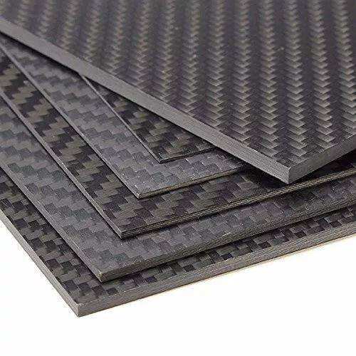
ການບັນລຸຄວາມກົດທີ່ເປັນເອກະພາບໃນແຕ່ລະຊັ້ນເປັນເລື່ອງທີ່ຄ່ອນຂ້າງກວ້າງຂວາງ. ສາມາດນຳໃຊ້ວິທີການຫຼາຍຢ່າງເພື່ອບັນລຸການຈັດສົ່ງຄວາມກົດຢ່າງເໝາະສົມ, ແລະ ວິທີທຳອິດແມ່ນການປ່ຽນທິດທາງຂອງຊັ້ນໂດຍໃຊ້ຊັ້ນວັດສະດຸທີ່ມີທິດທາງດຽວ (single directional sheets) ໃນທິດທາງຂ້າມກັນທີ່ 0, 45 ແລະ 90 ອົງສາ. ວິທີນີ້ຈະເຮັດໃຫ້ທັງກຳລັງກົດ (compressive forces) ແລະ ກຳລັງດຶງ (tensile forces) ຖືກດູດຊຶມໄດ້ຢ່າງເໝາະສົມໂດຍຊັ້ນວັດສະດຸທີ່ມີຢູ່ ໃນທິດທາງທີ່ຖືກຈັດເປັນຊັ້ນ, ແລະ ສາມາດຮັກສາຄວາມສົມດຸນຂອງຄວາມເຄັ່ງຕຶງ (stresses) ໂດຍການປ້ອງກັນບໍ່ໃຫ້ຈຸດທີ່ອ່ອນແອໃນເຂດເປົ້າໝາຍລົ້ມສະລາຍ. ເມື່ອນຳໃຊ້ວິທີນີ້ ໄດ້ບັນທຶກວ່າມີຄວາມແຂງແຮງຫຼາຍກວ່າເຫຼັກເຖິງ 18 ເທົ່າ. ໃນກໍລະນີທີ່ຮູບຮ່າງຂອງຊິ້ນສ່ວນມີຄວາມສັບສົນສູງ, ເສັ້ນໄຟເຄີບອນທີ່ຖືກຈັກ (woven carbon fiber) ຈະເປັນທາງເລືອກທີ່ດີກວ່າ ເນື່ອງຈາກມັນມີເສັ້ນໄຟທີ່ເຮັດວຽກໃນຫຼາຍທິດທາງ ເນື່ອງຈາກວິທີການຈັກຂອງມັນ. ແລະ ເວລາທີ່ນຳໃຊ້ resin ໃນຂະບວນການ…
ແຕ່ລະຊັ້ນຕ້ອງຖືກກົດດ້ວຍລູກກະດິດ (roller) ເພື່ອໃຫ້ຖືກດູດຊຶມຢ່າງທົ່ວເຖິງ ແລະ ຂັບອາກາດອອກທັງໝົດ.
ຮັກສາຄວາມໜືດຂອງ resin (300–500 cPs) ເພື່ອໃຫ້ການລົ້ນໄຫຼເກີດຂຶ້ນຢ່າງຄາດການໄດ້ ແລະ ເພື່ອຫຼີກເວັ້ນບໍລິເວນທີ່ບໍ່ຖືກດູດຊຶມ (dry spots).
ຕ້ອງການຄວາມດັນທີ່ເພີ່ມຂຶ້ນໃນລະຫວ່າງການຊ້ອນເພື່ອປ້ອງກັນການຈັດແຈງຄືນຂອງເຮືອນຢາງ ຫຼື ການຂາດເຮືອນຢາງ.
ໃນການຜະລິດຊີ້ນສ່ວນປະກອບທີ່ເຮັດຈາກວັດຖຸປະກອບ (composite component), ວິທີການໃຊ້ຖົງສູນຍາກາດ (vacuum bagging) ຍັງຄົງເປັນໜຶ່ງໃນວິທີທີ່ມີປະສິດທິຜົນທີ່ສຸດໃນການບັງຄັບໃຫ້ມີຄວາມກົດດັນທີ່ເທົ່າທຽມກັນທົ່ວທຸກຊັ້ນ, ເນື່ອງຈາກວ່າມັນເຮັດໃຫ້ຊັ້ນຕ່າງໆຖືກບີບຢ່າງເປັນຮູບປະຈຳ ແລະ ຂັບອາກາດອອກຈາກຊ່ອງຫວ່າງລະຫວ່າງຊັ້ນເມື່ອຖົງຖືກດຶງໃຫ້ຕຶງ. ເມື່ອຜູ້ຜະລິດໃຊ້ລະບົບຟີລ໌ມທີ່ໄວຕໍ່ຄວາມກົດດັນ (pressure-sensitive film system), ພວກເຂົາສາມາດເຫັນເຖິງບໍລິເວນທີ່ມີການບັງຄັບຄວາມກົດດັນຢ່າງມີປະສິດທິຜົນໄດ້ຢ່າງຊັດເຈນ, ເຊິ່ງຕາມການສຶກສາທີ່ຜ່ານມາ ສາມາດຂັບອາກາດອອກໄດ້ເຖິງ 90% ຂອງຊ່ອງຫວ່າງທັງໝົດ. ເມື່ອເຮືອນ (resin) ໄດ້ແຫ້ງຕົວແລ້ວ, ມີຄວາມເປັນໄປໄດ້ທີ່ຈະກວດສອບຊີ້ນສ່ວນທີ່ສຳເລັດແລ້ວດ້ວຍເຄື່ອງກວດສອບທີ່ໃຊ້ແສງທີ່ຖືກຂັດກັນ (crossed polarizers). ນີ້ເຮັດໃຫ້ສ່ວນທີ່ມີເຮືອນເກີນໄປ ແລະ ບໍລິເວນທີ່ເສັ້ນໃຍບໍ່ຖືກຊຸ່ມຢ່າງພໍເທົ່າທີ່ຈະເຮັດໄດ້ເຫັນໄດ້ຢ່າງຊັດເຈນ, ເຊິ່ງເປັນສັນຍານບ່ອນທີ່ມີບັນຫາກັບຄວາມກົດດັນໃນຂະນະການຜະລິດ. ດ້ວຍການປະສານງານຮ່ວມກັນຂອງຂະບວນການເຫຼົ່ານີ້, ຈະສາມາດຮັບປະກັນໄດ້ວ່າຊີ້ນສ່ວນທີ່ຜະລິດອອກມາຈະມີຄຸນນະພາບສູງ, ມີຄວາມໜາທີ່ເທົ່າທຽມກັນ, ມີສັດສ່ວນຂອງເສັ້ນໃຍ ແລະ ເຮືອນທີ່ຖືກຕ້ອງຕາມເປົ້າໝາຍ, ແລະ ມີປະສິດທິຜົນທີ່ຄາດຄະເນໄດ້ ແລະ ເຊື່ອຖືໄດ້ຢ່າງແທ້ຈິງໃຕ້ສະພາບການເຄື່ອນໄຫວທີ່ຮຸນແຮງຂອງການຜະລິດໃນອຸດສາຫະກຳການບິນ ແລະ ອຸດສາຫະກຳລົດຍົນ.
ພາກ FAQ
ເປັນຫຍັງການໃຊ້ຄວາມດັນທີ່ເທົ່າທຽມກັນຈຶ່ງມີຄວາມສຳຄັນຢ່າງຍິ່ງໃນຂະບວນການລາມິເນດແຜ່ນໄຟເບີກາໂບນ?
ຄວາມດັນທີ່ເທົ່າທຽມກັນເຮັດໃຫ້ມີການລົ້ນໄຫຼຂອງເຣຊິນຢ່າງສອດຄ່ອງ ແລະ ການປຸກລວມຂອງເສັ້ນໃຍຢ່າງເທົ່າທຽມກັນ ເຊິ່ງເຮັດໃຫ້ເກີດການຕິດຕາມທີ່ແຂງແຮງ ແລະ ສົ່ງເສີມຄວາມແຂງແຮງຂອງຊິ້ນສ່ວນ.
ບັນຫາໃດທີ່ອາດເກີດຂື້ນຈາກຄວາມດັນທີ່ບໍ່ເທົ່າທຽມກັນໃນຂະບວນການລາມິເນດ?
ຄວາມດັນທີ່ບໍ່ເທົ່າທຽມກັນອາດເຮັດໃຫ້ເກີດບໍລິເວນທີ່ມີຮ່ອງຫວ່າງ (voids) ແລະ ບໍລິເວນທີ່ແຫ້ງ (dry areas) ແລະ ຄວາມໜາທີ່ບໍ່ເທົ່າທຽມກັນ ແລະ ອາດເຮັດໃຫ້ຄວາມແຂງແຮງຕໍ່ການດຶງ (tensile strength) ແລະ ຄວາມໝັ້ນຄົງທາງໂຄງສ້າງລົດຖຸກຫຼຸດລົງ.
ສິ່ງໃດທີ່ສາມາດເຮັດໄດ້ເພື່ອປັບປຸງຄວາມດັນໃນບ່ອນຂຶ້ນຮູບໃນຂະບວນການລາມິເນດ?
ການເລືອກວັດສະດຸທີ່ເໝາະສົມສຳລັບບ່ອນຂຶ້ນຮູບ ການຄວບຄຸມການຂະຫຍາຍຕัวຈາກຄວາມຮ້ອນ ແລະ ການປັບຮູບຂອງຮູບຮ່າງຫ້ອງຂຶ້ນຮູບໃຫ້ເໝາະສົມຮ່ວມກັບການຈັດວາງຊ່ອງລະบายອາກາດຢ່າງເໝາະສົມ ຈະຊ່ວຍໃຫ້ບັນລຸເປົ້າໝາຍນີ້.
ວິທີການໃດທີ່ສາມາດນຳໃຊ້ເພື່ອຊ່ວຍໃນການຕິດຕາມຂະບວນການລາມິເນດໃນເວລາຈິງ?
ວິທີການຕິດຕາມຄວາມດັນ ແລະ ອຸນຫະພູມໃນເວລາຈິງນັ້ນໃຊ້ເຊີນເຊີທີ່ອີງໃສ່ເອຟີກົດ (piezoelectric sensors) ແລະ ເຕັກນິກການຖ່າຍຮູບອຸນຫະພູມດ້ວຍແສງອິນຟາເຣດ (infrared thermography).
ວິທີໃດທີ່ສາມາດນຳໃຊ້ເພື່ອເຮັດໃຫ້ຄວາມເປັນເອກະພາບຂອງຄວາມກົດດັນຕໍ່ແຜ່ນໄຍເຄີບອນ (carbon fiber) ມີຄວາມສູງສຸດ?
ການນຳໃຊ້ລູກກະລິງທີ່ມີຟັນ, ການຄວບຄຸມຄວາມໜືດຂອງເຣຊິນຢ່າງຖືກຕ້ອງ, ການເພີ່ມຄວາມກົດດັນຢ່າງຄ່ອຍເປັນຄ່ອຍ, ແລະ ການຫໍ່ດ້ວຍຖົງສູນຍາກາດ (vacuum bagging) ຊ່ວຍໃຫ້ບັນລຸເປົ້າໝາຍນີ້.
สารบัญ
- ການຈັດສົ່ງຄວາມກົດດັນທີ່ບໍ່ເທົ່າທຽມກັນມີຜົນຕໍ່ການຫຼືນຂອງເຮຊິນ ແລະ ການປະສົມປະສານຂອງໄຟເບີ
- ບໍ່ເຕັມ, ແຖບແຫ້ງ, ແລະ ຄວາມໜາທີ່ບໍ່ສອດຄ່ອງກັນ ອັນເກີດຈາກຄວາມແຕກຕ່າງຂອງຄວາມກົດດັນ.
- ຜົນກະທົບຂອງວັດສະດຸແມ່ພິມຕໍ່ການຂະຫຍາຍຕัวຈາກຄວາມຮ້ອນ ແລະ ການສູນເສຍຄວາມກົດດັນ
- ສິ່ງນີ້ຊ່ວຍໃນການຮັກສາຄວາມສະຖຽນຕໍ່ການປັບປຸງຢ່າງຕໍ່ເນື່ອງເພື່ອໃຫ້ເຂົ້າກັບຂໍ້ຈຳກັດທາງເລຂາຄະນິດທີ່ສັບສົນ.
- ການນຳໃຊ້ເຊັນເຊີທີ່ຝັງຢູ່ຮ່ວມກັບເທັກໂນໂລຊີການຖ่ายຮູບອຸນຫະພູມດ້ວຍແສງອິນຟຣາເຣັດ (IR Thermography)
- ແຕ່ລະຊັ້ນຕ້ອງຖືກກົດດ້ວຍລູກກະດິດ (roller) ເພື່ອໃຫ້ຖືກດູດຊຶມຢ່າງທົ່ວເຖິງ ແລະ ຂັບອາກາດອອກທັງໝົດ.
- ພາກ FAQ