
 EN
EN

The Anisotropy Imperative – Why Fiber Direction Defines Structural Performance
Unidirectional carbon fiber prepreg separates itself from woven fabrics by concentrating all reinforcing fibers in a single direction, creating extreme anisotropy. In the aligned direction, tensile strength exceeds 4,400 MPa, more than six times that of high-strength steel, while transverse strength is governed by the resin matrix and often falls below 10% of the longitudinal value. This stark contrast means even slight angular errors during layup shift load transfer from high-strength fibers to the weaker matrix, drastically reducing load-bearing capacity. A 5° misalignment lowers axial stiffness by 10 to 15%, since fiber force contribution scales with the cosine of the angle; at 10°, stiffness loss exceeds 30%. In multi-layer laminates designed for specific load states, misaligned plies also induce parasitic shear and bending stresses that accelerate delamination and matrix cracking, shortening fatigue life. Structural performance, therefore, is not merely a function of material quality but is directly governed by how precisely unidirectional prepreg layers are oriented relative to service loads. This fundamental dependency explains why high-performance sectors enforce rigorous alignment tolerances and why just a few degrees of deviation can transform a perfectly engineered laminate into a structurally compromised part. Alignment is not a secondary process detail; it is a primary design variable dictating final stiffness, strength, and durability.
Manual Registration vs. Laser-Guided Digital Ply Placement
Precise fiber alignment is the foundational step toward structural integrity in composite manufacturing. Because unidirectional carbon fiber prepreg derives nearly all its strength along the fiber axis, even small angular deviations compromise performance: a 10° error can cut stiffness by over 30%. Selecting an alignment method is thus an engineering decision, not an operational preference, balancing capital investment, throughput, and achievable accuracy. Manual registration relies on skilled technicians using physical templates, printed grids, and basic laser guides to align prepreg by hand. It offers flexibility for prototyping and low-volume, complex geometries but introduces variability: operator fatigue and process drift can cause inconsistencies exceeding ±2° across a single shift. In contrast, automated systems like Automated Fiber Placement use robotic end-effectors equipped with integrated laser projectors and photoelectric sensors to verify tow position and orientation in real time. These systems actively correct deviations, consistently achieving placement accuracies beyond human capability, enabling highly optimized structures with minimal safety margins. The main barriers to adoption remain significant capital cost and the need for specialized programming and maintenance expertise.
Tolerance Requirements – ±0.5° in Aerospace vs. ±1.5° in Automotive Applications
Alignment tolerances reflect application-specific performance requirements, not process limitations. Aerospace mandates ±0.5° for primary structures, driven by the need to maximize specific stiffness and prevent buckling in thin-walled components such as fuselage panels and wing skins. This precision is validated using optical metrology and is non-negotiable for certification. In contrast, the automotive industry accepts ±1.5° for high-volume structural parts like body-in-white reinforcements, a pragmatic trade-off reflecting cost-driven production constraints where cycle times must be measured in minutes, not hours. This tolerance allows faster layup rates and simpler tooling while still delivering substantial gains in stiffness and crash performance over metal alternatives, particularly where primary load paths are well-defined and less sensitive to fine directional optimization. Exceeding these tolerances carries serious consequences: in aerospace, deviations can lead to structural failure or significant weight penalties, while in automotive, misalignment reduces crash energy absorption and negatively impacts noise, vibration, and harshness performance. Primary alignment methods also differ, with aerospace relying on Automated Fiber Placement while automotive often employs manual or semi-automated layup.
Substrate Surface Preparation and Adhesion-Driven Slippage
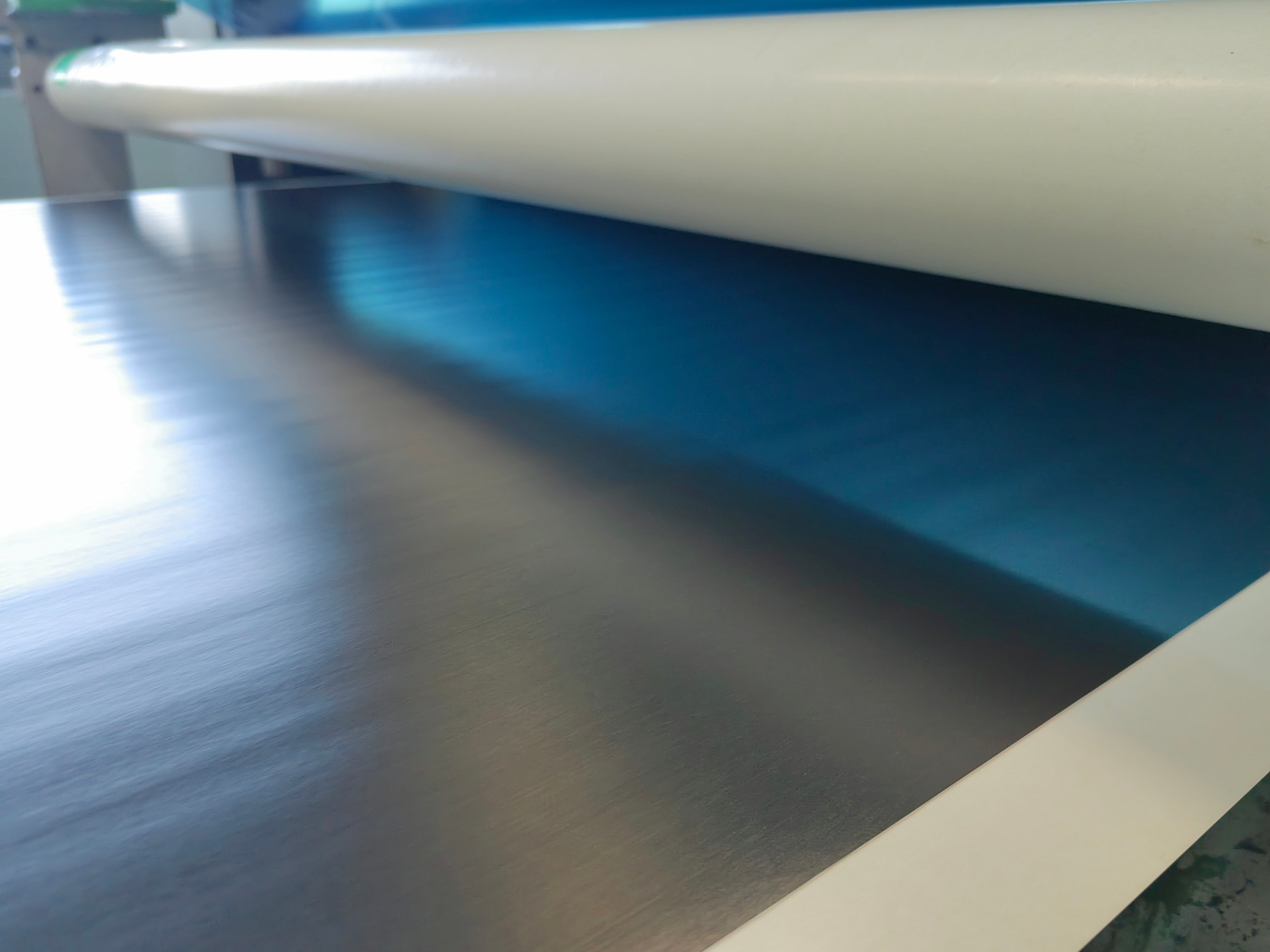
Even trace surface contamination, such as dust, oil, or moisture, can undermine prepreg positioning accuracy by reducing initial tack, permitting ply shift during debulking or handling. A clean, dry substrate is essential; chemical wipes or plasma treatments effectively remove low-surface-energy films. Industry processing audits indicate inadequate preparation can lower interlaminar shear strength by more than 15%. Operators must verify uniform adhesion before placing subsequent plies, using standardized tack-testing coupons and real-time visual inspection to catch slippage early. Without consistent surface quality, local fiber misorientation accumulates, directly eroding laminate performance.
Thermal Expansion Mismatch and Real-Time Fiber Direction Drift
Tooling and prepreg rarely share identical coefficients of thermal expansion. During heated debulking or cure, differential expansion induces shear stress that rotates fibers out of alignment, especially problematic in long, narrow parts where cumulative misalignment may exceed 1°. In-situ monitoring using thermal cameras and laser sensors enables detection and correction before resin gelation locks in errors. Low-CTE tooling materials, such as Invar or carbon composite molds, minimize mismatch. Yet even with perfect initial alignment, operators must account for dynamic movement during heating; otherwise, embedded fiber waviness degrades both strength and stiffness.
Validating Alignment with Optical Metrology
Process control remains incomplete without objective, quantitative verification of layup accuracy. Human visual inspection cannot reliably detect deviations below 2°, yet structural models show a 5° misalignment reduces component stiffness by up to 20%. This performance gap has accelerated adoption of optical metrology systems that digitize the verification workflow. Modern systems project structured light onto each ply immediately after placement. High-resolution cameras capture surface texture, and fiber orientation analysis generates a full-field deviation map within seconds. A 2023 industry benchmark found automated optical inspection reduced defect escape rates by 68% compared to manual checks alone, identifying invisible flaws like ply bridging, gaps, and localized fiber waviness. The resulting data creates a digital twin of the as-built laminate, enabling engineers to correlate final part performance with measured fiber architecture, supporting precise failure analysis and iterative process refinement. For safety-critical applications, traceable alignment data is increasingly a contractual requirement, not an optional quality enhancement.
Frequently Asked Questions
Why is unidirectional fiber alignment critical in carbon fiber prepreg? Alignment is critical because unidirectional carbon fiber derives nearly all its strength from fibers aligned along the load direction. Even slight misalignment compromises structural integrity by shifting load-bearing capacity from the fibers to the weaker resin matrix.
What is the acceptable alignment tolerance in high-performance applications like aerospace? Aerospace applications typically require a ±0.5° tolerance to ensure maximum stiffness and reduce buckling risks, particularly in thin-walled structures.
How does thermal expansion mismatch affect fiber alignment? Differential thermal expansion between tooling and prepreg can induce shear stress and rotate fibers out of alignment during heating processes, degrading the final structure's strength and stiffness.
Can optical metrology systems detect small fiber alignment errors? Yes, modern optical metrology systems can detect alignment errors as small as 2°, offering precise deviation maps for quality control and process improvement.
Why are alignment tolerances more stringent in aerospace compared to automotive industries? Aerospace demands higher precision due to the need to maximize component stiffness and prevent buckling. Automotive applications typically allow ±1.5°, balancing speed and cost requirements with an acceptable level of structural performance.